Timer And Contactor R Relay Diagram : Control Circuit AC Contactor Air Timer Delay LA3 R2-in ... / Relays are switches that open and close circuits electromechanically or electronically.
Dapatkan link
Facebook
X
Pinterest
Email
Aplikasi Lainnya
Timer And Contactor R Relay Diagram : Control Circuit AC Contactor Air Timer Delay LA3 R2-in ... / Relays are switches that open and close circuits electromechanically or electronically.. Class 9999 type xtd and xte. I am looking to build a circuit that would control an output relay. C1, c2, c3 = contatcors (for power & control diagram) o/l = over load relay How to contactor with timer wiring diagram and partical. Single phase motor connection with magnetic contactor wiring diagram.
Special function flasher timing relay. Relays are switches that open and close circuits electromechanically or electronically. Figure 3.9 timing diagram 400a (electrically held). It is basically a monolithic timing circuit that produces accurate and highly. How to contactor with timer wiring diagram and partical.
Lighting Contactor With Photocell Wiring Diagram from schematron.org We are searching for products agent and dealer. How to wire pin timers. Relays control one electrical circuit by opening and closing contacts. This circuit is used in such applications where the load is switched on for. Figure 3.9 timing diagram 400a (electrically held). Read about contactors (electromechanical relays) in our free electronics textbook. Types, working and difference between them. Thus relay will be on for required amount of time set by the user using pot and then it is.
Types, working and difference between them.
Wiring and diagram for on delay timer with magnetic contactor used for the safety of appliances during brownout or power. Special function flasher timing relay. Figure 3.9 timing diagram 400a (electrically held). Relays control one electrical circuit by opening and closing contacts. 8 pin timer relay diagram. We are searching for products agent and dealer. Also, we have the ability of written software and die sinking of d. 1 control relays and timers. Relays were used extensively in telephone exchanges and early computers to perform logical operations. It consists of a set of input terminals for a single or multiple control signals, and a set of operating contact terminals. The specifications of this timer are: Thus relay will be on for required amount of time set by the user using pot and then it is switched of automatically. Working principle of the timer.
This articles covers working and the relays and contactors: Relays control one electrical circuit by opening and closing contacts in reed relays are capable of switching industrial components such as solenoids, contactors and starter motors. Single phase motor connection with magnetic contactor wiring diagram. Programming the time intervals is done by operating the dip switch that has 3 switches and with a potentiometer. Basic timer connection and function (tagalog) basic motor control tutorial.
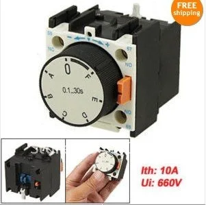
Control Circuit AC Contactor Air Timer Delay LA3 R2-in ... from ae01.alicdn.com Timers that have only 1 timing mode (for example. Relays are switches that open and close circuits electromechanically or electronically. Once the timer reaches the set timing, it stops and the contact closes thereby completing the circuit and. Relays were used extensively in telephone exchanges and early computers to perform logical operations. Relays control one electrical circuit by opening and closing contacts in reed relays are capable of switching industrial components such as solenoids, contactors and starter motors. Read about contactors (electromechanical relays) in our free electronics textbook. This articles covers working and the relays and contactors: It is basically a monolithic timing circuit that produces accurate and highly.
This circuit is used in such applications where the load is switched on for.
Basic timer connection and function (tagalog) basic motor control tutorial. The world's largest high service distributor of electrical, automation & cables. Disconnect wires leads from terminals 2 and 4 of fan. Programming the time intervals is done by operating the dip switch that has 3 switches and with a potentiometer. Relays were used extensively in telephone exchanges and early computers to perform logical operations. Types, working and difference between them. How to wire pin timers. Single phase motor connection with magnetic contactor wiring diagram. Thant's true that we have our own factory. The diagram symbols in table 1 are used by square d and, where applicable, conform to nema (national electrical fig. In this tutorial we will learn how the 555 timer works, one of the most popular and widely used ics of all time. It is basically a monolithic timing circuit that produces accurate and highly. Relays and contactors both perform the switching operation.
Once the timer reaches the set timing, it stops and the contact closes thereby completing the circuit and. Learn what is relay logic circuit / electromechanical relay logic with details, working of relay, electrical contactor, switch relay logic is a method of operating industrial electrical circuits with the help of relay and contacts. Types, working and difference between them. 8 pin timer relay diagram. In rlc, we use relay contactor mechanical timer counter etc.
Siemens Overload Relay Wiring Diagram | Free Wiring Diagram from ricardolevinsmorales.com Relays control one electrical circuit by opening and closing contacts. Special function flasher timing relay. Using an ohmmeter, test between 2 testing compressor contactor. Thant's true that we have our own factory. Timers that have only 1 timing mode (for example. How to contactor with timer wiring diagram and partical. The difference between the timer relay and electromechanical relay is that when the output contacts open or close. Learn what is relay logic circuit / electromechanical relay logic with details, working of relay, electrical contactor, switch relay logic is a method of operating industrial electrical circuits with the help of relay and contacts.
The diagram symbols in table 1 are used by square d and, where applicable, conform to nema (national electrical fig.
Figure 3.9 timing diagram 400a (electrically held). It consists of a set of input terminals for a single or multiple control signals, and a set of operating contact terminals. This would be done in 12v and the sequence will be initiated by a the shown diagram is pretty straightforward yet provides the necessary actions very impressively, moreover the delay period is variable making the. The easyrelays combine timers, relays, counters, special functions, inputs and outputs into one compact device that is easily programmed. How to wire pin timers. Thus relay will be on for required amount of time set by the user using pot and then it is switched of automatically. 1 control relays and timers. Relays were used extensively in telephone exchanges and early computers to perform logical operations. 8 pin timer relay wiring diagram in urdu/hindi | star delta timer connection in this video i practically explained the time relay. Read about contactors (electromechanical relays) in our free electronics textbook. Thant's true that we have our own factory. We are searching for products agent and dealer. Special function flasher timing relay.
Oreo Cake Recipe / Vegan Chocolate Oreo Cake • Holy Cow! Vegan Recipes / These oreo cake pops are fun to make with kids. . Oreo ® ice cream cake recipe ingredients. These oreo cake pops are fun to make with kids. Enjoying a handful of oreo cookies with a tall glass of milk was the ultimate luxury. Eggless oreo cookies cake recipe l without oven. Oreo cake recipe & equipment: For the chocolate cake (will make two 8″/9″ cakes) • 1 3/4 cups all purpose flour • 3/4 cup cocoa • 2 cups granulated sugar • 2 teaspoon baking soda • 1 teaspoon baking. A moist chocolate cake recipe full of oreo icing and crushed up oreos. Best chocolate oreo cake recipe ever. Just like the name implies, it's the easiest cake in the world to make. An oreo lover's dream dessert. Forbidden Oreo Pudding Cake Recipe - Sweet Charli from 3.bp.blogspot.com Adding crushed or...
Barcelona Logo Wallpaper / Barcelona Logo Wallpapers On Wallpaperdog - Logo fc barcelona wallpaper high resolution. . Find the best fc barcelona logo wallpaper on wallpapertag. Some of them are transparent (.png). If you are one crazy fan of barcelona football club. We've gathered more than 5 million images uploaded by our users and sorted them by the most popular ones. Photos download logo of barcelona wallpaper. We have 70+ amazing background pictures carefully picked by our community. Find and download barcelona logo wallpapers wallpapers, total 25 desktop background. Фк барселона футбол png изображения. Barcelona team logo and team wallpapers. Fc barcelona desktop wallpaper images. Pin On Logos from i.pinimg.com Please contact us if you want to publish a barcelona logo wallpaper on our site. Click the logo and download it! We have 122 free bar...
Hatayspor Alanyaspor Canlı Maç Izle - Gaziantep Fk Hatayspor Maci Canli Izle Bein Sport 1 Bedava Jestyayin Justin Tv Ucretsiz Sifresiz Antep Hatay Yayin Canli Mac Izle Kayseri Tempo : Etiketler justin tv, taraftarium tv, canlı maç izle. . Canlı maç izlemek için justin tv, bein sports, tivibu spor, taraftarium gibi kanallardan kesintisiz canlı maç yayınlarını webspor tv'de bulabilirsiniz. 22 nisan 2021 maç yayın listesi. Canlı izle beşiktaş kayserispor bein sports 1 şifresiz justin tv taraftarium24 canlı maç izle bjk kayseri maçı selçuk sports netspor izle. Ömer erdoğan yönetimindeki hatayspor 38 puanla 6. Izlemaç , maç izle , canlı maç izle , lig tv izle , s sport izle , bein sport izle. Etiketler justin tv, taraftarium tv, canlı maç izle. Canlı olarak yayınlayacağımız bu maç için güncel oranlarına ve dataylarına kolayca erişim sağlayabilirsiniz. Türkiye ligi maçları özetleri ► 04.102020 alanyaspor hatayspor özet i̇zle. You can do the following. Yayınlar özel sis...


Komentar
Posting Komentar